What Is Resistance Welding And How Does It Work?
What Is Resistance Welding?
Factors Affecting Resistance Welding
Types Of Resistance Welding
Importance in Manufacturing
Applications
Equipment and Components
How To Choose The Right Welding Process?
FAQ:
If you’re new to resistance welding or looking for a clearer understanding of it, then you definitely need to read this article carefully. This article will take you deep into the world of resistance welding. Whether you’re a beginner or looking to expand your knowledge, this article will provide you with valuable insights.
What Is Resistance Welding?
Resistance welding is a high-speed, economical metal joining method. This welding technique is suitable for lap joints, butt joints, or joints that do not require air tightness, with thicknesses less than 6mm for thin sheet structures. Of course, it can also weld thicker and larger metal workpieces, but its overall performance may not be as good as certain other welding methods.
Definition and Basics
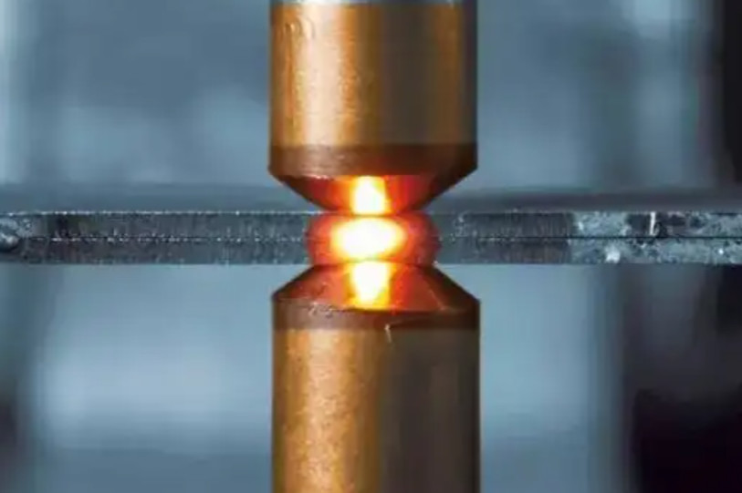
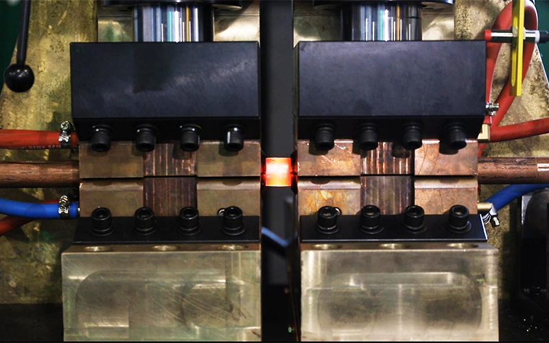
Resistance welding is a method where the workpieces to be joined are placed between two electrodes. By passing current through the workpieces and the contact points, resistance heating occurs, generating heat at the junction of the workpieces. This localized heating causes the area to melt or become pliable, while pressure from the two electrodes bonds the metal together.
When current flows through a conductor, it generates heat due to resistance. The higher the resistance when the current is constant, the more heat is produced. At the point where metals are in contact, the resistance is much greater than within the metal itself. Therefore, when a large current passes through the contact between the metal and the electrode, the metal quickly heats up due to the immense heat. At this point, the metal becomes highly ductile, and with applied pressure, the two pieces of metal securely bond together.
Resistance Welding Working Principle
The principle of resistance spot welding and the formation of joints are illustrated in Figure 1-1. Metal A and metal B are placed between two electrodes, and pressure is applied to the electrodes. A powerful current is passed between the two electrodes by the transformer of the resistance welder. The contact surfaces of the workpieces form a physical contact point, which gradually expands as the current heats it up. Plastic deformation and heat continuously activate the atoms at the contact point, leading to the formation of a molten core. The molten core grows in the form of columnar crystals, pushing out the higher alloy concentration components towards each other. When the electrodes of the welder move away from the metal surface, and the metal cools down, the workpieces are welded together, creating a strong metal bond. The joint surface disappears, leaving behind the weld nugget.
1-1
Factors Affecting Resistance Welding
Resistance welding is a welding method that uses electrical current to generate heat to join metal components. As mentioned earlier, the principle of resistance welding mainly stems from Joule’s law of heating, where the generation of welding heat is primarily determined by parameters such as current, resistance, and welding time. It can be expressed by the following formula:
Q = I²Rt
Meaning of each welding parameter:
Q — Heat (J)
I — Welding current (A)
R — Resistance (Ω)
t — Welding time (s)
Welding Current
The current has a significant impact on the heat generated during welding, as shown in the formula. The square value of the current affects the heat, meaning that the higher the current, the faster the heat will increase. Therefore, when adjusting welding parameters before welding, it is crucial to set the appropriate current. If the welding current is too small, the weld will not melt, and no fusion core will form. If the current is too large, the fusion core will rapidly grow, causing excessive spattering during welding and damaging the electrodes.
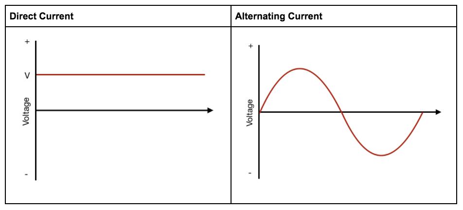
Welding current is mainly divided into alternating current (AC) and direct current (DC), as shown in the diagram below. The spot welding machines we use are also divided into direct current spot welding machines and alternating current spot welding machines. Direct current spot welding machines use three-phase power supply, ensuring balanced power distribution, and can achieve welding frequencies of over 1000 Hz, resulting in high welding accuracy. They also have the advantage of low power demand from the power grid, making these energy-saving welders increasingly popular among manufacturing industry manufacturers. Alternating current spot welding machines have a single-phase 50Hz output, high continuous load capacity, and high requirements for the power grid. Additionally, they have low welding power, requiring longer welding times.
Contact Resistance
From the formula, it’s easy to see that resistance is directly proportional to the heat generated. The higher the resistance, the greater the heat produced during welding. Resistance is distributed throughout various parts of the electrode and workpiece. During welding, the highest resistance occurs at the contact point of the workpiece, resulting in the highest heat generation. Next is the resistance at the contact point between the workpiece and the electrode. However, since the electrode is water-cooled and quickly cools down, the temperature decreases rapidly. On the other hand, the contact resistance between the workpieces, although it disappears, has poor heat dissipation, leading to high temperatures. Therefore, only a small area between the workpieces can reach the temperature necessary to form a fusion core and weld together.
Additionally, temperature and electrode pressure affect the resistance. As the temperature rises, the metal yield strength decreases, increasing the contact area between the workpieces and between the workpiece and the electrode, resulting in decreased resistance. Increasing electrode pressure makes the workpiece surface smoother, enlarging the contact area and reducing resistance. As a result, there is a phenomenon where, during welding of typical materials, the resistance increases shortly after powering on, and when the power is turned off and the fusion core forms, the resistance starts to decrease.
Welding Time
The longer the welding time, the higher the heat generated. In this formula, current and time can complement each other. When you want a strong weld, you can set a high current for a short time to generate heat quickly and form a fusion core to complete the welding. Alternatively, you can set a low current for a longer time, but there’s a limit to this approach. If the time is set too long, it can lead to excessive spattering and may cause the electrode to stick. Whether it’s current or time, there are limitations. When setting parameters, you need to consider the material and thickness of the workpiece, as well as the power of the welding machine.
Material Properties
The material of the workpiece largely affects its resistivity, which plays an important role in welding heat generation. When welding stainless steel, which has high resistivity and poor thermal conductivity, it’s easier to generate heat but harder to dissipate it, so smaller currents are needed. When welding aluminum alloys with low resistivity and good thermal conductivity, it’s harder to generate heat but easier to dissipate it, so larger currents are required. Metals like silver and copper have high thermal conductivity and low resistivity, so even with high currents, they don’t generate much heat but can conduct it away. Therefore, these metals are not suitable for resistance welding but can be used as electrode materials.
Electrode Design and Geometry
The shape and material of the electrode also affect heat generation. The contact area between the electrode and the workpiece affects the current density. Frequent use of electrodes can lead to wear and deformation, increasing the contact area and reducing welding strength. Therefore, we need to repair and replace the electrode tips promptly. The thermal conductivity and resistance of the electrode affect heat transfer. Therefore, we should choose materials with good thermal conductivity and low resistance.
Surface Preparation
The shape and material of the electrodes also affect heat generation. The contact area between the electrode and the workpiece affects the current density. When our electrodes are used frequently and wear out, it increases the contact area, leading to reduced welding strength. Therefore, we need to repair and replace electrode tips promptly. The thermal conductivity and resistivity of the electrodes affect heat transfer. Therefore, we should choose materials with good thermal conductivity and low resistivity.
Types Of Resistance Welding
Due to different product specifications and requirements for welding, different resistance welding processes are used to complete the task. Resistance welding can be divided into spot welding, projection welding, seam welding, and butt welding based on the welding process.
Spot Welding
Spot welding is a welding method where metal is pressed together by upper and lower electrodes and welded by passing current through it. It’s a traditional form of resistance welding, simple to operate, and requires relatively low skill levels from workers. Due to its unique welding process, spot welding is the primary choice for welding metal components in aerospace engineering and is widely used in welding automotive body and other components. It’s typically used for welding thin sheets of low carbon steel, aluminum, stainless steel, galvanized steel, and other thin plates, typically around 3 millimeters thick.
Seam Welding
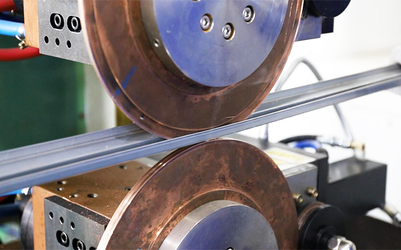
Seam welding typically involves joining the edges of two metal components. The two metal workpieces are placed between two roller electrodes. While one electrode rolls and applies pressure, continuous or intermittent discharge occurs. Heat generated at the electrode’s rolling point melts the workpieces and joins them together, forming a continuous weld seam. This method is widely used for welding metal parts requiring sealed joints. Since the welding area is relatively long, to prevent misalignment, we usually use spot welding for positioning before seam welding.
Projection Welding
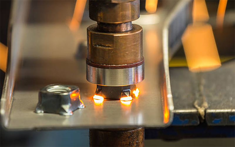
Projection welding is a variation of spot welding, where the formation of the weld point is similar to spot welding, but projection welding is typically used for workpieces with raised points. The presence of these raised points limits the area through which the current passes, increasing the current density in the welding area. This concentrated heating facilitates the connection of the joint. This welding method is known as projection welding. Projection welding can form one or more fusion cores at the joint at once. During welding, the current required for projection welding at the same weld point is less than that for spot welding. However, before each projection is crushed, the current needs to melt the projection; otherwise, there may be a significant amount of spatter. Projection welding can be used to weld nuts, bolts, or plates with raised points and is widely used in the manufacturing of electronic and automotive components.
Butt Welding
Butt welding involves aligning the end faces of two metal workpieces, placing them between electrodes, securely fastening the two workpieces, and using high current to generate heat, melting the contact surface of the workpieces and joining them together. Butt welding is further divided into flash butt welding and resistance butt welding.
Flash butt welding is a rapid welding process that uses high current to quickly melt the workpieces, applying pressure to form a solid-phase connection. It is commonly used for welding large cross-sectional areas of metal rods, sheets, and pipes, with maximum areas reaching 20,000mm² and above. During the discharge welding process, sparks are produced at the contact point, hence the name flash butt welding. It can weld high carbon steel, stainless steel, aluminum alloys, and can also weld dissimilar metals such as copper and aluminum.
Resistance butt welding uses resistance heat to bring the workpiece joints to a plastic state at high temperatures, completing the welding process with forging force. It is suitable for welding joints with cross-sectional areas within 250mm², often used for welding small cross-section metal wires, rods, and strips.
Importance in Manufacturing
- Resistance welding does not require the addition of metal during the welding process, resulting in high welding efficiency and minimal pollution.
- Due to its consistency and stability, resistance welding is easy to automate, seamlessly integrating with automation to further enhance production efficiency and save labor.
- Compared to other welding methods, resistance welding is cost-effective. Firstly, the equipment cost for resistance welding is relatively low, and secondly, there is minimal material waste during the resistance welding process. This significantly reduces production costs for manufacturers in the manufacturing industry.
- Resistance welding is widely used across various industries and is particularly indispensable in sectors such as aerospace, automotive manufacturing, and more.
- Resistance welding is suitable for welding various types of metals in the manufacturing industry, including stainless steel, carbon steel, aluminum, copper, and more, making it versatile in its application.
Applications
Resistance welding is widely used, mainly in industries such as automotive components, aerospace, electronics, and heavy industry. As the demand for welded metal components in various industries continues to grow, higher standards for welding technology have been set, driving the progress and development of resistance welding.
Automotive Industry Applications
In automobile manufacturing, where safety and stability are paramount, resistance welding is a commonly used welding method. It is frequently employed for joining various metal components in car bodies, such as roofs, doors, metal sheets, and metal nuts. Resistance welding offers high efficiency, stable welding quality, and is easily automated, making it an indispensable process in the automotive manufacturing industry.
Aerospace Industry Applications
Resistance welding is frequently used to connect metal components in aircraft and rockets, such as joining aircraft wings and fuselages, as well as various small metal parts. These components must possess high strength and durability, with stringent requirements for the quality of the joints, which is where resistance welding excels. Resistance welding plays a crucial role in the aerospace industry, and advancements in this field are also facilitated by the aerospace sector.
Electronics Industry Applications
Resistor welding is commonly used for electronic components and certain metal parts in electronic devices. It offers high welding precision and is suitable for connecting miniature components like electronic chips and wires. In today’s rapidly evolving era of electronic devices, resistor welding accelerates the assembly of electronic components, driving industry advancement.
Heavy Industry Applications
Resistance welding is often used for welding large metal components in bridges and buildings, such as bridge bottom flanges and steel reinforcement. It is also utilized in the manufacturing of large machinery to connect metal parts. With its efficient and stable welding technology, resistance welding has become one of the important processing methods in heavy industry. It ensures the safety of heavy equipment and structures.
Equipment and Components
Welding Machines
Resistance welding machines are divided into four main categories: spot welding machines, projection welding machines, seam welding machines, and butt welding machines, based on different processes. Choose the appropriate welding equipment according to the characteristics of materials and shapes.
Electrodes
The electrode is an important component to ensure welding quality. The main materials for welding electrodes are: chromium zirconium copper, aluminum oxide copper, beryllium cobalt copper, tungsten, molybdenum, graphite, etc. Depending on the different workpieces being welded, electrodes are divided into flat electrodes, spherical electrodes, nut electrodes, bolt electrodes, etc. Typically, electrode fixation involves tapered fitting, with taper ratios mostly in 1:10 and 1:5.
Cooling Systems
During operation, resistance welding machines require circulating water to cool components like electrodes and transformers. Therefore, we install a cooling system for resistance welding machines. The cooling water temperature should be below 30°C. If the temperature is too high, it may trigger a protective shutdown of the welding machine. It’s best to use impurity-free cooling water for circulation to prevent water stains and pipe blockages.
How To Choose The Right Welding Process?
The choice of welding method depends on many factors.
Workpiece Thickness and Shape: Different welding methods are suitable for workpieces of varying thicknesses and shapes. For example, resistance welding is generally only suitable for welding thin metal sheets, while oddly shaped and thick workpieces are usually welded using arc welding.
Welding Quality Requirements: The desired welding quality also dictates the choice of welding method. For workpieces requiring high sealing and joint strength, welding methods that meet these requirements should be selected.
Production Efficiency and Cost: If high annual production volume is required, selecting a welding method with high efficiency is necessary. Cost considerations should also be taken into account.
Environmental Factors: Some welding methods generate waste materials and emissions, causing environmental pollution. Therefore, environmental considerations should be taken into account when selecting a welding method.
FAQ:
What are the limitations of resistance welding?
Resistance welding is not suitable for welding large metal components.
How do you ensure safety in resistance welding?
When operating resistance welding, wear a safety helmet and safety goggles.
How can I get trained in resistance welding?
You can undergo training at a resistance welding manufacturer.
What are the main quality problems of resistance welding joints?
Cold solder joint, inadequate strength, welding deformation, oxidation.
Inspection methods for resistance welding joints
Destructive testing, microscopic examination, visual inspection, metallographic testing, ultrasonic testing.

